Technology
The Elimination Flow Behind the Casing - the Basis of Safe Oil and Gas Wells Operation
Demakhin S.A., Merkulov A.P., Tufanov I.A., Malajko S.V., Klochkov A.V. (Zirax LLC, Zirax-Nefteservice LLC, SPE Oil-engineering LLC)
One of the topical problems of wells safe operation is the flow behind the casing. This phenomenon poses a threat to the wellhead pressure loss, casing integrity damage, blowout, cratering, emergence of formation an anthropogenic deposits.
The problem of flow behind the casing is often found in wells operating practices, for example, more than 8000 wells in the Gulf of Mexico have such problem, about 50% of oil wells at the offshore White Tiger field in Vietnam, almost 30% of wells of gas condensate sulfurous Karachaganak field in Kazakhstan. In Russia, about 25-30% of all production wells of Gazprom PJSC, and even 50% at the Northern fields, are wells with the flow behind the casing of various volumes. At the gas fields in the North of Tyumen region, after putting wells into commercial development, flow gas behind the casing shows and cratering were detected at the wellhead of more than 50% of the production wells [1].
Abandonment of wells with the flow behind the casing is a serious problem. According to various estimates, currently around 900 suspended and subject to abandonment wells have the flow behind the casing, from abandoned around 3600 wells are subject to repeated abandonment as dangerous for the environment.
Thus, the flow behind the casing is widespread, but currently there is little technology that allow to steadily solve the problem of reducing or eliminating the flow behind the casing. While in accordance with article 1196 of "Safety regulations in the oil and gas industry", in case of detection of pressure behind the casing operation of well must be stopped.
Causes of the flow behind the casing are mainly [1-3]:
- leaks of casing (pipes, threads) and casing head;
- formation of the channels in the cement stone during the well construction phase;
- crack formation in cement stone during perforation, hydraulic pressure testing, tool rotation in the casing, temperature fluctuations in well, etc.
- geological factors (high reservoir pressure, structural damage of geological material).
The particular relevance of the flow behind the casing problem can be seen at the gas and gas condensate fields, formation fluid of which contains aggressive and toxic hydrogen sulfide. For example, at the Astrakhan gas and condensate field (AGCF) the problem of the flow behind the casing arose before the start of commercial operation. The flow behind the casing was in exploratory wells, in 70 wells it was discovered after drilling completion - during the field development, in 59 wells it occurred during operation. Therefore, since the beginning of the AGCF development it became urgent to define the causes and the risk of such complication, and development of technologies for reducing and eliminating the flow behind the casing.
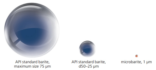
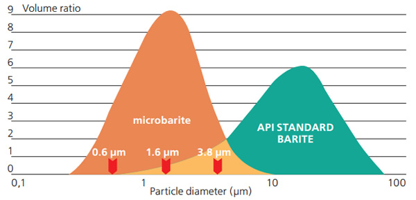
One such technology is successfully applied, including at the AGCF, is the gravitational method based on the application of the special fluid with density of 2.1-2.3 g/cm3. It is a suspension of microbarite with particle size of about 1 μm (fig. 1 and 2) in a liquid solution of surfactants and solvents. By virtue of good penetration this fluid is able to be filtered in the space between casing and surface casing or conductor and further, due to high density of solution, to deter the flow of gas to the surface.
 Fig. 1. Size comparison of microbarite with a standard barite
 Fig. 2. Diameter comparison of microbarite particles with a standard barite
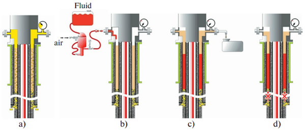
Technology of the flow behind the casing liquidation using microbarite based fluid provides a series of operations. At the first stage, microbarite based fluid is pumped (fig. 3, b) into space between casing and surface casing with broken cementing, where formation fluid enters (fig. 3, a). At the second stage, the fluid because of its density (2.1-2.3 g/cm3) gravitationally replaces formation fluids in the space between casing and surface casing, in cracks and channels in the cement stone (fig. 3, c) and stops the flow of formation fluids through this space (fig. 3, d).
 Fig. 3. The flow behind the casing elimination technology on the basis of microbarite containing fluid
Advantage of this technology, unlike the upload the methods of injecting hardening materials into the space between casing and surface casing, is a manageable impact, this space is not blocked completely and forever. Any hardening material in time is subject to chemical, thermal and mechanical degradation. So the recurrence of pressure in the space between casing and surface casing is quite possible, but at the same time to inject something else in this space will be very difficult. The application of the microbarite based fluid leaves the space between casing and surface casing open for action, fluid can be removed or replaced with a new batch.
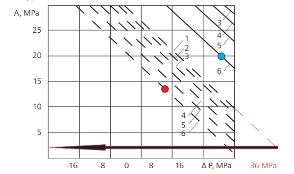
Another feature of the impact on the space between casing and surface casing is its small injectivity, sometimes it is problem to inject any amounts of fluid in it. To intensify this process special wellhead power waves generators are used in order to create pulsating pressure in the flow of injected fluid and facilitate its penetration into the space between casing and surface casing, in fractures and channels in the cement stone. It is important not to disturb the existing strength of the cement stone, its contact with the metal of a pipe. Therefore, the parameters of the vibration exposure are specially chosen taking into account this factor. Fig. 4, shows the nomogram for determining allowable pulsating pressure on given excessive static pressure. It is designed for the different b/a parameters (b - outer radius, a - inner radius of casing) that are corresponding to used in oilfield practice set of 148 mm and 168 mm casings.
 Fig. 4. Nomogram for determining allowable amplitude of vibration pressure on backfill cement stone depending on the excess static pressure Δ P (repression or depression).
- - - - for «hot» cement;
------- for «cold» cement;
The value of the b/a parameter: 1 – 1.167; 2 – 1.16; 3 – 1.15; 4 – 1.14; 5 – 1.125; 6 – 1.105.
Nomogram shows that vibration fatigue [4], for example, for “cold” cement will be achieved by creating 20 MPa repression at 20 MPa amplitude of vibration pressure, and for "hot" cement and even the most thin-walled casing (b/a = 1.105) vibration fatigue at 6.0 MPa repression will be achieved at 13.5 MPa amplitude of vibration pressure (see points on the chart).
When carrying out repair and insulation works to eliminate the flow behind the casing using pneumatic vibrator hydro impulsive pressure fluctuation with an amplitude of 1.2-2.2 MPa and repression of not more than 6 MPa vibration fatigue will not be achieved at more than 6 times ratio of the reserve for "hot” cement.
Thus, the flow behind the casing elimination technology of Zirax using suspensions of microbarite is an effective way of extending the safe operation of oil and gas wells.
References
- Gorbacheva O.A. Development and implementation of methods for monitoring and research of wells with the flow behind the casingat the Astrakhan GCF: PhD in Technical Sciences thesis. - Ufa, 2012. -193 p.: ill.
- Tenn, Rudolf Alfredovich. Methods of diagnosis and elimination of the flow behind the casingduring the construction of wells and UGSF: PhD in Technical Sciences thesis: 05.15.10. - Stavropol, 1999. - 205 p.: ill.
- Phan Tien Zung. Battling the flow behind the casingin oil wells: PhD in Technical Sciences thesis: 25.00.15. - Ufa, 2006. -1 54 p.: ill.
- Dyblenko V.P., Kamalov R.N., Sharifullin R.Y., Tufanov I.A. Increased productivity and recovery of wells with application of vibrowave impact. - М.: Nedra-Businesscentre OOO, 2000. - 381 p.


